Inhaltsverzeichnis
ESP32 mit 868 MHz LoRa Modul
Gefunden habe ich dieses kompakte Mikrocontroller Modul mit ESP32, OLED Display und LoRa Funkmodul auf AliExpress. Ein solches Board kostet zum derzeitigen Stand (Dezember 2017) gerade mal 13 EUR, also gleich mal her damit 
Technische Daten
- Espressif ESP32 Mikrocontroller (ARM Dual-Core, Bluetooth LE, WiFi)
- Semtech SX1276 LoRa Transceiver
- 0.96„ OLED Display (blau)
- CP2102 USB-UART Konverter
- Eingangsspannung 3.3V bis zu 7V
Treiber
Das Module meldet sich unter Windows unter dem Namen „CP2102 USB to UART Bridge Controller“. Leider wird aber nicht automatisch ein Treiber für das Gerät gefunden, sodass der serielle Port zum Programmieren des Mikrocontroller nicht sofort zur Verfügung steht. Abhilfe schaffen die Treiber von Silicon Labs - dem Hersteller des USB→UART Konverters und die gibt es hier:
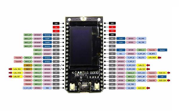
Pinout
PlatformIO
Will man das Board unter PlatformIO nutzen, so legt man einfach ein neues Projekt an und wählt dort „Heltec WiFi LoRa 32 (Heltec Automation)“ als „Board“ bei der Initialisierung eines neuen Projektes aus. Beim SDK wähle ich meist „Arduino“ - ist für mich einfacher, aber natürlich könnt ihr auch direkt „ESP-IDF“ verwenden.
OLED Display ansteuern
Um das eingebaute OLED Display anzusteuern, wird die allseits bekannte „u8g2“ Bibliothek verwendet. Mit
pio lib install u8g2
im PlatformIO Terminal, wird die entsprechende Bibliothek installiert.
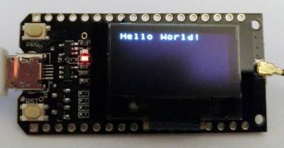
Jetzt einfach noch den folgenden Sketch reinkopieren und schon sieht man das „Hello World!“ Beispiel der Bibliothek auf dem Display des Moduls:
- 1 main.cpp
#include <Arduino.h>
#include <U8x8lib.h>

#define OLED_SCL 15   // GPIO 15
#define OLED_SDA  4   // GPIO  4
#define OLED_RST 16   // GPIO 16

// define the display type that we use
U8X8_SSD1306_128X64_NONAME_SW_I2C u8x8(/* clock=*/ OLED_SCL, /* data=*/ OLED_SDA, /* reset=*/ OLED_RST);

void setup() {
    // set up the display
    u8x8.begin();
    u8x8.setPowerSave(0);
}

void loop() {
    // Yay... a "Hello World!"
    u8x8.setFont(u8x8_font_chroma48medium8_r);
    u8x8.drawString(0,0,"Hello World!");
    delay(2000);
}
TTN mit ABP
Nachdem das Display ja schon läuft, ist es an der Zeit das Modul mit dem TTN zu verbinden. Ich habe für mein momentan zum Testen genutztes Single-Channel-Gateway erstmal nur ABP (Activation By Personalization) zur Anmeldung am Netzwerk verwendet. Da ich kein Fan von den Single-Channel-Gateways bin, werde ich aber einen Sketch zu OTAA (Over The Air Activation) noch nachreichen.
Zuerst muss die Arduino LMIC Bibliothek von IBM eingebunden werden. Das geht unter PlatformIO mit folgendem Befehl:
pio lib install 852
Die ID für die Arduino LMIC Bibliothek (ID = 852) kann man mit folgendem Befehl herausfinden:
pio lib search lmic
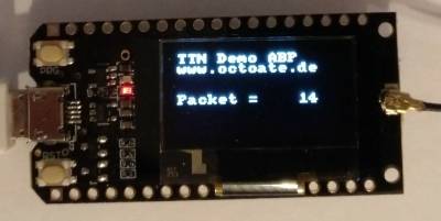
Der dazugehörige Sketch sendet einfach fortlaufend nummerierte Pakete mit dem Inhalt „Packet = <nr>“ an das TTN Gateway. Mein Sketch ist an dem ABP Beispiel der IBM LMIC Bibliothek angelehnt. In dem folgenden Beispielcode müsst ihr die entsprechenden TTN Schlüssel an eure selbst erstellte Anwendung natürlich anpassen. Wenn ihr kein Single-Channel-Gateway verwendet, solltet ihr außerdem die for-Schleife in der setup() Methode entfernen, da sie alle Channel außer Channel 0 deaktiviert, was bei einem richtigen Gateway keinen Sinn macht. Auf dem Modul sieht das dann so aus:
- 1 main.cpp
#include <Arduino.h>

// OLED
#include <U8x8lib.h>

// LMIC
#include <lmic.h>
#include <hal/hal.h>
#include <SPI.h>

// OLED Pins
#define OLED_SCL 15   // GPIO 15
#define OLED_SDA  4   // GPIO  4
#define OLED_RST 16   // GPIO 16

// LoRa Pins
#define LoRa_RST  14  // GPIO 14
#define LoRa_CS   18  // GPIO 18
#define LoRa_DIO0 26  // GPIO 26
#define LoRa_DIO1 33  // GPIO 33
#define LoRa_DIO2 32  // GPIO 32

// define the display type that we use
U8X8_SSD1306_128X64_NONAME_SW_I2C u8x8(/* clock=*/ OLED_SCL, /* data=*/ OLED_SDA, /* reset=*/ OLED_RST);

// LoRaWAN NwkSKey, network session key
static const PROGMEM u1_t NWKSKEY[16] = { 0xAA, 0x55, 0xAA, 0x55, 0xAA, 0x55, 0xAA, 0x55, 0x0E, 0xCC, 0x93, 0x3C, 0xAB, 0x0C, 0x24, 0x52 };

// LoRaWAN AppSKey, application session key
static const u1_t PROGMEM APPSKEY[16] = { 0xAA, 0x55, 0xAA, 0x55, 0xAA, 0x55, 0xAA, 0x55, 0xE6, 0x65, 0x0E, 0x4E, 0x14, 0x25, 0xF1, 0x5B };

// LoRaWAN end-device address (DevAddr)
static const u4_t DEVADDR = 0xAAFFAAFF ;

// These callbacks are only used in over-the-air activation, so they are
// left empty here (we cannot leave them out completely unless
// DISABLE_JOIN is set in config.h, otherwise the linker will complain).
void os_getArtEui (u1_t* buf) { }
void os_getDevEui (u1_t* buf) { }
void os_getDevKey (u1_t* buf) { }

static char mydata[14 + 1]; // "Packet = " + max(65536)
static uint16_t packetNumber = 0;
static osjob_t sendjob;

// Schedule TX every this many seconds (might become longer due to duty
// cycle limitations).
const unsigned TX_INTERVAL = 60;

// Pin mapping
const lmic_pinmap lmic_pins = {
    .nss = LoRa_CS,
    .rxtx = LMIC_UNUSED_PIN,
    .rst = LoRa_RST,
    .dio = { LoRa_DIO0, LoRa_DIO1, LoRa_DIO2 },
};

void do_send(osjob_t* j){
    // Check if there is not a current TX/RX job running
    if (LMIC.opmode & OP_TXRXPEND) {
        Serial.println(F("OP_TXRXPEND, not sending"));
    } else {
        // Prepare upstream data transmission at the next possible time.
        sprintf(mydata, "Packet = %5u", packetNumber);
        LMIC_setTxData2(1, (xref2u1_t)mydata, sizeof(mydata)-1, 0);
        Serial.println(F("Packet queued"));
        packetNumber++;
    }
    // Next TX is scheduled after TX_COMPLETE event.
}

void onEvent(ev_t ev) {
    Serial.print(os_getTime());
    Serial.print(": ");
    switch(ev) {
        case EV_SCAN_TIMEOUT:
            Serial.println(F("EV_SCAN_TIMEOUT"));
            break;
        case EV_BEACON_FOUND:
            Serial.println(F("EV_BEACON_FOUND"));
            break;
        case EV_BEACON_MISSED:
            Serial.println(F("EV_BEACON_MISSED"));
            break;
        case EV_BEACON_TRACKED:
            Serial.println(F("EV_BEACON_TRACKED"));
            break;
        case EV_JOINING:
            Serial.println(F("EV_JOINING"));
            break;
        case EV_JOINED:
            Serial.println(F("EV_JOINED"));
            break;
        case EV_RFU1:
            Serial.println(F("EV_RFU1"));
            break;
        case EV_JOIN_FAILED:
            Serial.println(F("EV_JOIN_FAILED"));
            break;
        case EV_REJOIN_FAILED:
            Serial.println(F("EV_REJOIN_FAILED"));
            break;
        case EV_TXCOMPLETE:
            Serial.println(F("EV_TXCOMPLETE (includes waiting for RX windows)"));
            if (LMIC.txrxFlags & TXRX_ACK)
              Serial.println(F("Received ack"));
            if (LMIC.dataLen) {
              Serial.println(F("Received "));
              Serial.println(LMIC.dataLen);
              Serial.println(F(" bytes of payload"));
            }
            // Schedule next transmission
            os_setTimedCallback(&sendjob, os_getTime()+sec2osticks(TX_INTERVAL), do_send);
            break;
        case EV_LOST_TSYNC:
            Serial.println(F("EV_LOST_TSYNC"));
            break;
        case EV_RESET:
            Serial.println(F("EV_RESET"));
            break;
        case EV_RXCOMPLETE:
            // data received in ping slot
            Serial.println(F("EV_RXCOMPLETE"));
            break;
        case EV_LINK_DEAD:
            Serial.println(F("EV_LINK_DEAD"));
            break;
        case EV_LINK_ALIVE:
            Serial.println(F("EV_LINK_ALIVE"));
            break;
         default:
            Serial.println(F("Unknown event"));
            break;
    }
}

void setup() {
    // init packet counter
    sprintf(mydata, "Packet = %5u", packetNumber);

    Serial.begin(115200);
    Serial.println(F("Starting"));

    // set up the display
    u8x8.begin();
    u8x8.setPowerSave(0);

    // LMIC init
    os_init();
    // Reset the MAC state. Session and pending data transfers will be discarded.
    LMIC_reset();

    // Set static session parameters. Instead of dynamically establishing a session
    // by joining the network, precomputed session parameters are be provided.
    #ifdef PROGMEM
    // On AVR, these values are stored in flash and only copied to RAM
    // once. Copy them to a temporary buffer here, LMIC_setSession will
    // copy them into a buffer of its own again.
    uint8_t appskey[sizeof(APPSKEY)];
    uint8_t nwkskey[sizeof(NWKSKEY)];
    memcpy_P(appskey, APPSKEY, sizeof(APPSKEY));
    memcpy_P(nwkskey, NWKSKEY, sizeof(NWKSKEY));
    LMIC_setSession (0x1, DEVADDR, nwkskey, appskey);
    #else
    // If not running an AVR with PROGMEM, just use the arrays directly
    LMIC_setSession (0x1, DEVADDR, NWKSKEY, APPSKEY);
    #endif

    // Set up the channels used by the Things Network, which corresponds
    // to the defaults of most gateways. Without this, only three base
    // channels from the LoRaWAN specification are used, which certainly
    // works, so it is good for debugging, but can overload those
    // frequencies, so be sure to configure the full frequency range of
    // your network here (unless your network autoconfigures them).
    // Setting up channels should happen after LMIC_setSession, as that
    // configures the minimal channel set.
    // NA-US channels 0-71 are configured automatically
    LMIC_setupChannel(0, 868100000, DR_RANGE_MAP(DR_SF12, DR_SF7),  BAND_CENTI);      // g-band
    LMIC_setupChannel(1, 868300000, DR_RANGE_MAP(DR_SF12, DR_SF7B), BAND_CENTI);      // g-band
    LMIC_setupChannel(2, 868500000, DR_RANGE_MAP(DR_SF12, DR_SF7),  BAND_CENTI);      // g-band
    LMIC_setupChannel(3, 867100000, DR_RANGE_MAP(DR_SF12, DR_SF7),  BAND_CENTI);      // g-band
    LMIC_setupChannel(4, 867300000, DR_RANGE_MAP(DR_SF12, DR_SF7),  BAND_CENTI);      // g-band
    LMIC_setupChannel(5, 867500000, DR_RANGE_MAP(DR_SF12, DR_SF7),  BAND_CENTI);      // g-band
    LMIC_setupChannel(6, 867700000, DR_RANGE_MAP(DR_SF12, DR_SF7),  BAND_CENTI);      // g-band
    LMIC_setupChannel(7, 867900000, DR_RANGE_MAP(DR_SF12, DR_SF7),  BAND_CENTI);      // g-band
    LMIC_setupChannel(8, 868800000, DR_RANGE_MAP(DR_FSK,  DR_FSK),  BAND_MILLI);      // g2-band

    // disable channels (only use channel 0 - 868.1 MHz - for my single channel gateway!!!)
    for (int channel = 1; channel <= 8; channel++) {
      LMIC_disableChannel(channel);
    }

    // Disable link check validation
    LMIC_setLinkCheckMode(0);

    // TTN uses SF9 for its RX2 window.
    LMIC.dn2Dr = DR_SF9;

    // Set data rate and transmit power for uplink (note: txpow seems to be ignored by the library)
    LMIC_setDrTxpow(DR_SF7, 14);

    // Start job
    do_send(&sendjob);
}

void loop() {
    u8x8.setFont(u8x8_font_amstrad_cpc_extended_r);
    u8x8.drawString(0, 0, "TTN Demo ABP");
    u8x8.drawString(0, 1, "www.octoate.de");

    u8x8.drawString(0, 4, mydata);

    os_runloop_once();
}
TTN mit OTAA
Natürlich funktioniert auch die Over The Air Activation (OTAA) mit dem Modul. Zur Nutzung des Sketches müsst ihr die gleichen Bibliotheken installieren, die bereits bei ABP verwendet wurden. Im folenden Sketch müsst ihr dann nur noch die APPEUI, die DEVEUI und den APPKEY eintragen. Die Werte dazu findet ihr in der TTN Konsole eures Devices.
- 1 main.cpp
#include <Arduino.h>
#include <stdlib.h>

// OLED
#include <U8x8lib.h>

// LMIC
#include <lmic.h>
#include <hal/hal.h>
#include <SPI.h>

// OLED Pins
#define OLED_SCL 15   // GPIO 15
#define OLED_SDA  4   // GPIO  4
#define OLED_RST 16   // GPIO 16

// LoRa Pins
#define LoRa_RST  14  // GPIO 14
#define LoRa_CS   18  // GPIO 18
#define LoRa_DIO0 26  // GPIO 26
#define LoRa_DIO1 33  // GPIO 33
#define LoRa_DIO2 32  // GPIO 32

// define the display type that we use
U8X8_SSD1306_128X64_NONAME_SW_I2C u8x8(/* clock=*/ OLED_SCL, /* data=*/ OLED_SDA, /* reset=*/ OLED_RST);

// This EUI must be in little-endian format, so least-significant-byte
// first. When copying an EUI from ttnctl output, this means to reverse
// the bytes. For TTN issued EUIs the last bytes should be 0xD5, 0xB3,
// 0x70.
static const u1_t PROGMEM APPEUI[8]= { 0xFF, 0xFF, 0xFF, 0xFF, 0xFF, 0xFF, 0xFF, 0xFF };
void os_getArtEui (u1_t* buf) { memcpy_P(buf, APPEUI, 8);}

// This should also be in little endian format, see above.
static const u1_t PROGMEM DEVEUI[8]= { 0xFF, 0xFF, 0xFF, 0xFF, 0xFF, 0xFF, 0xFF, 0xFF };
void os_getDevEui (u1_t* buf) { memcpy_P(buf, DEVEUI, 8);}

// This key should be in big endian format (or, since it is not really a
// number but a block of memory, endianness does not really apply). In
// practice, a key taken from ttnctl can be copied as-is.
// The key shown here is the semtech default key.
static const u1_t PROGMEM APPKEY[16] = { 0xFF, 0xFF, 0xFF, 0xFF, 0xFF, 0xFF, 0xFF, 0xFF, 0xFF, 0xFF, 0xFF, 0xFF, 0xFF, 0xFF, 0xFF, 0xFF };
void os_getDevKey (u1_t* buf) {  memcpy_P(buf, APPKEY, 16);}

static uint8_t mydata[] = "Hello, world!";
static osjob_t sendjob;

// Schedule TX every this many seconds (might become longer due to duty
// cycle limitations).
const unsigned TX_INTERVAL = 60;

// Pin mapping
const lmic_pinmap lmic_pins = {
    .nss = LoRa_CS,
    .rxtx = LMIC_UNUSED_PIN,
    .rst = LoRa_RST,
    .dio = { LoRa_DIO0, LoRa_DIO1, LoRa_DIO2 },
};

void showDatarate()
{
    switch (LMIC.datarate)
    {
        case DR_SF7:
            u8x8.drawString(0, 2, "DR_SF7");
            break;

        case DR_SF8:
            u8x8.drawString(0, 2, "DR_SF8");
            break;

        case DR_SF9:
            u8x8.drawString(0, 2, "DR_SF9");
            break;

        case DR_SF10:
            u8x8.drawString(0, 2, "DR_SF10");
            break;

        case DR_SF11:
            u8x8.drawString(0, 2, "DR_SF11");
            break;

        case DR_SF12:
            u8x8.drawString(0, 2, "DR_SF12");
            break;
    }
}

void showFrequency()
{
    //u8x8.drawString(0, 3, LMIC.txChnl);
    char frequency[10];
    itoa(LMIC.freq, frequency, 10);
    u8x8.drawString(0, 3, frequency);
}

void do_send(osjob_t* j){
    // Check if there is not a current TX/RX job running
    if (LMIC.opmode & OP_TXRXPEND) {
        Serial.println(F("OP_TXRXPEND, not sending"));
    } else {
        showDatarate();
        showFrequency();

        // Prepare upstream data transmission at the next possible time.
        LMIC_setTxData2(1, mydata, sizeof(mydata)-1, 0);
        Serial.println(F("Packet queued"));
    }
    // Next TX is scheduled after TX_COMPLETE event.
}

void onEvent (ev_t ev) {
    Serial.print(os_getTime());
    Serial.print(": ");
    switch(ev) {
        case EV_SCAN_TIMEOUT:
            Serial.println(F("EV_SCAN_TIMEOUT"));
            break;
        case EV_BEACON_FOUND:
            Serial.println(F("EV_BEACON_FOUND"));
            break;
        case EV_BEACON_MISSED:
            Serial.println(F("EV_BEACON_MISSED"));
            break;
        case EV_BEACON_TRACKED:
            Serial.println(F("EV_BEACON_TRACKED"));
            break;
        case EV_JOINING:
            Serial.println(F("EV_JOINING"));
            u8x8.drawString(0, 1, "JOINING");
            break;
        case EV_JOINED:
            Serial.println(F("EV_JOINED"));

            // Disable link check validation (automatically enabled
            // during join, but not supported by TTN at this time).
            u8x8.drawString(0, 1, "JOINED");
            LMIC_setLinkCheckMode(0);
            break;
        case EV_RFU1:
            Serial.println(F("EV_RFU1"));
            break;
        case EV_JOIN_FAILED:
            Serial.println(F("EV_JOIN_FAILED"));
            break;
        case EV_REJOIN_FAILED:
            Serial.println(F("EV_REJOIN_FAILED"));
            break;
            break;
        case EV_TXCOMPLETE:
            Serial.println(F("EV_TXCOMPLETE (includes waiting for RX windows)"));
            if (LMIC.txrxFlags & TXRX_ACK)
              Serial.println(F("Received ack"));
            if (LMIC.dataLen) {
              Serial.println(F("Received "));
              Serial.println(LMIC.dataLen);
              Serial.println(F(" bytes of payload"));
            }
            // Schedule next transmission
            os_setTimedCallback(&sendjob, os_getTime()+sec2osticks(TX_INTERVAL), do_send);
            break;
        case EV_LOST_TSYNC:
            Serial.println(F("EV_LOST_TSYNC"));
            break;
        case EV_RESET:
            Serial.println(F("EV_RESET"));
            break;
        case EV_RXCOMPLETE:
            // data received in ping slot
            Serial.println(F("EV_RXCOMPLETE"));
            break;
        case EV_LINK_DEAD:
            Serial.println(F("EV_LINK_DEAD"));
            break;
        case EV_LINK_ALIVE:
            Serial.println(F("EV_LINK_ALIVE"));
            break;
         default:
            Serial.println(F("Unknown event"));
            break;
    }
}

void setup() {
    // set up the display
    u8x8.begin();
    u8x8.setPowerSave(0);
    u8x8.setFont(u8x8_font_chroma48medium8_r);

    Serial.begin(115200);
    Serial.println(F("Starting"));

    #ifdef VCC_ENABLE
    // For Pinoccio Scout boards
    pinMode(VCC_ENABLE, OUTPUT);
    digitalWrite(VCC_ENABLE, HIGH);
    delay(1000);
    #endif

    // LMIC init
    os_init();

    // Reset the MAC state. Session and pending data transfers will be discarded.
    LMIC_reset();
    LMIC_setClockError(MAX_CLOCK_ERROR * 1 / 100);
    // Set up the channels used by the Things Network, which corresponds
    // to the defaults of most gateways. Without this, only three base
    // channels from the LoRaWAN specification are used, which certainly
    // works, so it is good for debugging, but can overload those
    // frequencies, so be sure to configure the full frequency range of
    // your network here (unless your network autoconfigures them).
    // Setting up channels should happen after LMIC_setSession, as that
    // configures the minimal channel set.

    LMIC_setupChannel(0, 868100000, DR_RANGE_MAP(DR_SF12, DR_SF7),  BAND_CENTI);      // g-band
    LMIC_setupChannel(1, 868300000, DR_RANGE_MAP(DR_SF12, DR_SF7B), BAND_CENTI);      // g-band
    LMIC_setupChannel(2, 868500000, DR_RANGE_MAP(DR_SF12, DR_SF7),  BAND_CENTI);      // g-band
    LMIC_setupChannel(3, 867100000, DR_RANGE_MAP(DR_SF12, DR_SF7),  BAND_CENTI);      // g-band
    LMIC_setupChannel(4, 867300000, DR_RANGE_MAP(DR_SF12, DR_SF7),  BAND_CENTI);      // g-band
    LMIC_setupChannel(5, 867500000, DR_RANGE_MAP(DR_SF12, DR_SF7),  BAND_CENTI);      // g-band
    LMIC_setupChannel(6, 867700000, DR_RANGE_MAP(DR_SF12, DR_SF7),  BAND_CENTI);      // g-band
    LMIC_setupChannel(7, 867900000, DR_RANGE_MAP(DR_SF12, DR_SF7),  BAND_CENTI);      // g-band
    LMIC_setupChannel(8, 868800000, DR_RANGE_MAP(DR_FSK,  DR_FSK),  BAND_MILLI);      // g2-band
    // TTN defines an additional channel at 869.525Mhz using SF9 for class B
    // devices' ping slots. LMIC does not have an easy way to define set this
    // frequency and support for class B is spotty and untested, so this
    // frequency is not configured here.

    // Disable link check validation
    LMIC_setLinkCheckMode(0);

    // TTN uses SF9 for its RX2 window.
    LMIC.dn2Dr = DR_SF9;

    // Set data rate and transmit power for uplink (note: txpow seems to be ignored by the library)
    //LMIC_setDrTxpow(DR_SF11,14);
    LMIC_setDrTxpow(DR_SF9,14);

    // Start job (sending automatically starts OTAA too)
    do_send(&sendjob);
}

void loop() {
    u8x8.setFont(u8x8_font_amstrad_cpc_extended_r);
    u8x8.drawString(0, 0, "TTN Demo ABP");
    u8x8.drawString(0, 1, "www.octoate.de");

    os_runloop_once();
}
Links
- Single-Channel-Gateway - https://github.com/kersing/ESP-1ch-Gateway-v5.0


